
Delligatti Associates is offering the OCSMP Accelerator™ SysML Training Course in an online, on-demand format. Participants in this online course have contacted me to ask questions either to get more details about a particular topic or to get clarification on points I made during a lesson. I have created this blog post to capture their questions and my answers in a single location for the benefit of the MBSE community. I will update this blog post with additional questions as I receive them.
The questions and answers are in reverse order so that returning visitors do not have to scroll through the old ones to get to the new ones. I hope you find this resource to be beneficial in your study of SysML. I welcome any feedback you may have.
Please connect with me on LinkedIn and Facebook and follow me on Twitter. You can also reach me by e-mail at ldelligatti@delligattiassociates.com.
Question 16:
For an operation, what is the difference between a parameter with direction set to return and a parameter with direction set to out? I see that an operation can have at most one return parameter. So, if I am modeling an operation which passes back multiple parameters, should I use parameters with direction set to out? Then, what is return for?
Answer:
A return parameter is a special output parameter—one whose values get passed back to the caller only upon completion of the operation (more precisely, upon completion of the method—i.e., the behavior—associated with the operation). By contrast, a parameter with direction set to “out” could provide values back to the caller even during the execution of the method associated with the operation. But that would only be possible if the corresponding output parameter of the method is marked as streaming (i.e., isStream = true). If the corresponding output parameter is nonstreaming, then the method (and thus the operation) would have to complete in order for values to be passed back to the caller via that output parameter.
I hope this helps.
Question 15:
I had a question related to checkpoint question 1-9 in the OCSMP Accelerator™ online course. In this question we consider the standard port and the nonatomic flow port as structural elements that we must consider when we count the number of structural elements. Why should we consider a standard port–which specifies ‘required services’ or ‘provided services’–to be a structural element? Previously on checkpoint question 1-6–which was related to behavioral features–we had to include the behavioral features of the standard port ‘DVD player’.
Answer:
A standard port is in fact classified as a structural feature in the UML metamodel. (To clarify, a SysML standard port is semantically equivalent to a UML port—and so I have to cite the UML metamodel to answer your question.) A standard port (like a flow port) represents a distinct point of interaction at the boundary of the owning block. For example, a standard port could represent a valve at the boundary of a tank…or a network interface card (NIC) at the boundary of a client workstation…or a shared memory segment at the boundary of a software process…or a SharePoint website at the boundary of a business organization. The standard port itself does in fact represent a structural element in your system design.
You can then optionally assign interfaces to a standard port. Those interfaces would generally contain a set of behavioral features (i.e., operations and receptions). Those behavioral features represent the behaviors that the owning block either provides or requires at that associated standard port. But the standard port itself is not a behavioral feature—it’s a structural feature.
In Question 1-6, you were asked to count the operations and receptions that the owning block implements–not the ports. Operations and receptions are behavioral features. The ports are not.
I hope this answer is clear and helpful.
Please note that–as of SysML v1.3–standard ports and flow ports became deprecated language features. SysML v1.3 introduced the unified concept of a port–which combines the capabilities of a standard port and a flow port into one. And you can optionally stereotype a port as either a full port or a proxy port to specify additional semantics. I invite you to take a look at Appendix B of SysML Distilled for a more in-depth discussion of ports post-SysML v1.3. For all new models that you need to create, I recommend using the new kinds of ports–not standard ports and flow ports. I cover standard ports and flow ports in SysML Distilled and in the OCSMP Accelerator™ course only because the current versions of the OCSMP certification exams still cover these topics. If you wish to earn the OCSMP certification, you still need to know about the old kinds of ports (until the exams get revised).
Question 14:
Why doesn’t the SysML standard require SysML tools to auto-check for compatibility between model elements? I am running into such issues in my work. How do you suggest dealing with these challenges?
Answer:
Let me answer each question separately.
Why doesn’t the SysML standard require SysML tools to auto-check for compatibility between model elements?
The SysML standard simply defines the grammar and vocabulary of the language, which determine whether the models that you—the end user of a modeling tool—create are well-formed or ill-formed. And if a particular modeling tool is implemented in a way that enables you—the end user—to create well-formed SysML models, then that tool is deemed to be “SysML compliant.” But enabling you to create well-formed models is not the same as prohibiting you from creating ill-formed models. A tool can be deemed “SysML compliant” even if it permits you to do things that are illegal in SysML.
With that said, SysML compliant tools do—in many cases—stop you from doing things that are illegal. For example, MagicDraw will not let you select a block to be the type of a value property—only a value type can be the type of a value property—and so MagicDraw will only list value types for you to pick from at that moment in the modeling process.
And sometimes a modeling tool will let you do things that are illegal, but give you a warning (with some visual cue on the screen) that you’re doing something illegal. For example, MagicDraw will highlight a part property in red on an IBD if you drag-and-drop it to a location on the diagram that’s outside of its owning context.
And sometimes a modeling tool will let you do things that are illegal without giving you a warning—like connecting two ports that do not have compatible types. And when a tool allows this (without at least warning you) it is unfortunate (and may be the basis for choosing another vendor’s tool in the next trade study you perform), but it does not make that tool non-SysML compliant.
Small comfort to you and your team, I know.
How do you suggest dealing with these challenges?
All of the commercial-grade modeling tools do provide an API, enabling you and your team to write custom code to query and manipulate a SysML model programatically. And so, when a modeling tool fails to implement a desired capability natively (like checking for port compatibility), your team can write custom code to do it. This does put extra burden on your team—a burden that some teams simply cannot take on due to their existing workload—but it is an option that you can exercise…when the perceived benefit of a new capability outweighs the cost of implementing it yourself.
I know this is not an entirely satisfactory answer, but I hope you find this information to be valuable.
Question 13:
Do you think there are essential elements of a model that must be present for it to really be MBSE?
Answer:
There is not an essential set of elements that a given model must have for your practice to truly be called MBSE. But…
There are certain kinds of elements that I would expect all models to have for there to be any real value in the practice of MBSE (and I’m inferring that this is the question you intended).
For example:
- I would expect all models to have a set of blocks to represent the system-of-interest and its components.
- I would expect all models to have a set of value types to represent the types of matter, energy, or data that flow through the system.
- I would expect all models to have at least some system behaviors defined…in the form of activities, interactions, or state machines. (Activities are the most common kind of behavior that modelers create first.)
That’s the bare minimum set of elements that I would expect all systems models to have. And I would hope that they additionally have the following kinds of elements:
- Use cases—to represent the system’s externally visible behaviors (i.e., the goals that actors achieve via the system)
- Actors—to represent the people and systems that are external to the system-of-interest and must interface with it to achieve their goals
- Constraint blocks—to represent the mathematical model that binds the system’s structures to provide assertions about nominal system behavior
- Operations (owned by blocks)—to represent the set of behaviors that each structure provides to its clients
- Interactions—to represent the set of test cases you will execute to verify that the system satisfies its requirements
And if your organization writes text-based requirements, I would also hope that your SysML model contains those requirements, too. Having those requirements in your SysML model enables you to establish traceability from those requirements to the various structural and behavioral elements that satisfy and verify those requirements. Establishing requirements traceability within your SysML model enables you to use your SysML modeling tool to automate requirements gap analysis and downstream impact analysis, and also enables the autogeneration of requirements traceability and verification matrices (RTVMs).
I said “if” at the beginning of that sentence because not all systems engineering methods (or organizational processes) dictate that you must write text-based requirements. You could alternatively create use cases in lieu of functional requirements and constraint blocks in lieu of non-functional requirements…in which case, please see my bullets above. With that said, text-based requirements remain standard fare in most systems engineering organizations today, and so I thought I should mention it.
But now I’ve gone well beyond what you actually asked. Still, I hope that this additional information is useful to you.
Question 12:
Does SysML support simulation? Because simulation is the key for detecting defects early.
Answer:
I agree. Simulation is the key to detecting defects early. And yes, SysML (and SysML modeling tools) do support both behavioral simulation and specialty engineering analyses.
All of the commercial-grade SysML modeling tools support these capabilities. However, the core modeling tools generally do not have a built-in simulation engine; you would have to either purchase the vendor’s add-on that provides the simulation engine or integrate your SysML modeling tool with an IDE (for behavioral simulation) or an equation-solving tool (for engineering analyses) that you already have installed in your development environment. But the short answer is: Yes, both SysML and SysML modeling tools support both of these capabilities.
With respect to behavioral simulation, you would begin by specifying behaviors in your SysML model (which are represented on activity diagrams, sequence diagrams, and state machine diagrams). These behaviors could then be executed directly by the tool’s simulation engine add-on. Alternatively, you can autogenerate source code from those behaviors and feed that source code to an integrated IDE to compile and run it.
With respect to specialty engineering analyses, you would begin by creating a parametric model in SysML (which is represented on a combination of block definition diagrams and parametric diagrams). That parametric model would then be fed to an integrated equation-solving tool to execute the engineering analyses.
These are powerful capabilities that are enabled by the practice of MBSE…and are fully supported by SysML and SysML modeling tools.
Question 11:
In reading SysML Distilled, these two bolded statements early in the book stood out to me:
“A diagram of the model is never the model itself; it is merely one view of the model.”
“You cannot conclude that a feature doesn’t exist from its absence on a diagram; it may be shown on another diagram of the model or on no diagram at all.”
This has been one of a few things about modeling that has concerned me. If I am looking for, or want to be aware of, some feature or element of the design and it is not on a diagram somewhere, how do I ever know about it? If something is “in the model” but not viewable, does it really exist? What does “in the model” really mean then?
Answer:
Let me separate this into two questions and address each one separately:
If I am looking for, or want to be aware of, some feature or element of the design and it is not on a diagram somewhere, how do I ever know about it?
The premise of this question is that the stakeholder wants to know about the existence of a particular element in the design. Given that premise, the modeling team should in fact display that element on at least one diagram somewhere to convey that piece of the design to the stakeholder.
Occasionally (not often) modelers will add elements to the model that no stakeholder necessarily needs to see on a diagram. For example, I may add a package import relationship to the model solely for the purpose of autogenerating source code with the respective “import” statement at the top of the source code file. In such a case, I may not need to display that package import relationship on any diagrams.
So that leaves modelers with the fundamental question: which elements should they show on a particular diagram and which elements should they leave off?
The key point about a diagram (and the answer to this question) is: each diagram that a modeler creates should have a specific purpose; each diagram should address specific concerns of specific stakeholders. A modeler should, therefore, show on a given diagram all of the elements necessary (and only the elements necessary) to address those identified concerns of those identified stakeholders.
And when (not if)—over the course of the systems life cycle—the design team identifies new stakeholders (or new concerns of existing stakeholders), they simply create new diagrams (or revise existing diagrams) as necessary to address those newly identified concerns.
Simply put: modeling (and diagramming) begin with knowing your target audience and their concerns. You model (and diagram) with a purpose—a purpose that the team defines in a modeling project plan at the beginning of the project…and continually revisits and refines as the systems life cycle progresses.
Now to your more fundamental (and philosophical) question:
If something is “in the model” but not viewable, does it really exist?
Yes.
At the risk of being somewhat glib, I must repeat:
Yes.
In this context, that phrase “not viewable” means “not on at least one diagram of the model.”
And so the answer to your question is unequivocally “yes.”
The model is a persistent set of metadata, representing your team’s design decisions. The model is its own engineering artifact with an existence separate and distinct from any diagrams that the modeling team creates to provide views of that model.
A modeling team will create both the model (i.e., the metadata) and a set of diagrams to view that model using a dedicated modeling tool (e.g., MagicDraw, Rhapsody, Enterprise Architect, Artisan Studio, UModel, Agilian). And all of it gets stored as files on a file system somewhere. When you open those files in a dedicated modeling tool, the model (i.e., the metadata) is rendered in the form of a model hierarchy, which appears in a model browser (which shows up in one pane in the modeling tool window). In the main pane of the modeling tool window, you will see one or more diagrams that the modeling team created to provide views of the model.
And the key point in all of this is summed up by what I refer to in SysML Distilled as the Fundamental Precept of Model-Based Engineering (which you excerpted in your question):
“A diagram of the model is never the model itself; it is merely one view of the model.”
You can absolutely add an element to the model (i.e., specify metadata that gets stored persistently in a file) and decide not to display it on any diagrams (for whatever reason). And that model element absolutely does exist.
It’s “in the model.” You can locate that model element in the model browser at any time. You can manually navigate to it by descending in the model hierarchy tree to the package where the element is located (if you already know where it’s located). Alternatively, you can find the element using a keyword search (if you know at least part of its name).
It’s “in the model” and it does exist…even if you’ve never dragged-and-dropped it onto any diagrams.
Thank you for your questions. I hope that my answers (though verbose) have clarified what makes model-based systems engineering (MBSE) different from the traditional document-based approach to engineering—specifically, this fundamental distinction between “model” and “diagram.”
Question 10:
I have a question about the use case specifications that you describe on page 79 of SysML Distilled. My question centers on what or whom is starting the use case. On one hand, we have the primary actor that invokes the use case, and on the other hand, we have a trigger that gets the use case started. The action taken by the actor and trigger sound very similar. Is it true that the act of invoking the use case is in fact the event which causes the use case to get started? Should “trigger” be seen as the event that stimulates the actor to invoke the use case?
Answer:
The trigger for a use case is, in fact, an event that you specify. But the triggering event doesn’t stimulate the primary actor to invoke the use case. The causal relationship goes in the other direction: the primary actor causes the triggering event to occur, which invokes the use case. And the triggering event generally occurs as a result of some action on the part of the primary actor.
The concept of a use case trigger is perhaps better understood inductively than deductively. Here are some examples of triggers that you might insert into a text use case specification:
- “User holds the power button for three seconds.”
- “Customer inserts a debit card into the ATM machine.”
- “The supply vessel sends a ‘low level’ signal to the shutoff valve.”
Hopefully this answer clarifies the concept. However, if you would like a more in-depth discussion of text use case specifications (and triggers), I recommend Alistair Cockburn’s excellent book, Writing Effective Use Cases.
Question 9:
A block can have an operation. I assume the operation can be an action and/or an activity, correct?
Answer:
An operation can’t be an action or an activity; it’s a behavioral feature of a block, not a behavior itself…and certainly not an action within a behavior. However, it can have a behavior associated with it–what we formally refer to as the method of the operation. (Note: “method” in this context does not connote software.) The method of an operation is simply the behavior that you, the modeler, select for that operation as the one that will get executed when a client block calls that operation (in the providing block). And of course, the behavior that you select as the method of an operation can be any one of the three kinds of behaviors defined in SysML: an activity, an interaction, or a state machine. (Activities and interactions are far more common than state machines as methods of operations.) So, the short answer to your question is: an operation can have an activity as its method; it cannot have an action (within an activity) as its method.
But perhaps you’re thinking of the special kind of action (that can appear in an activity) that’s known as a call operation action.
A call operation action represents a call that an activity makes to an operation of a block that you’ve created somewhere in your system model. And as I mentioned above, the operation that gets called could have a behavior associated with it as the method that gets executed.
A call behavior action, by contrast, is a special kind of action (that can appear in an activity), which represents a call that an activity makes directly to another behavior that you’ve created somewhere in your system model.
A call operation action and a call behavior action have something in common: they both convey behavioral decomposition. They both convey that a calling activity invokes some other behavior that you’ve defined in your model. The difference between them is in the number of degrees of separation from the calling activity to the called behavior.
With a call behavior action, there are only two degrees of separation:
- The calling activity has a call behavior action.
- The call behavior action has a behavior associated with it (that you select as the one that gets called).
With a call operation action, there are three degrees of separation:
- The calling activity has a call operation action.
- The call operation action has an operation (of a block) associated with it (that you select as the one that gets called).
- The called operation can have a behavior associated with it (that you select as the method that gets executed).
That’s the difference between them. So, why use a call behavior action versus a call operation action in an activity?
Call behavior actions do not link the behavioral model of your system to the structural model of your system. It’s a direct link from one behavior to another.
Call operation actions do link the behavioral model of your system to the structural model of your system; you’re linking a behavior (an activity) to a structure (a block with an operation)…which then has a link to another behavior.
The specific kind of action you choose to add to a given activity should be based on your team’s modeling methodology, which derives from the model purpose and model scope that are defined in your team’s modeling project plan.
(This was a bit of a tangent to your original question, but hopefully a related and worthwhile discussion.)
Question 8:
Four years back, I led an SE effort with a key stakeholder in which our first step was to document what they wanted (services from the system of interest) with SysML use cases (diagrams plus Cockburn-style text files), based on discussion of a context diagram (typical DoDAF-style OV-1). Those use cases became the foundation from which we developed the rest of the project artifacts. As I listened to you during the Module 4 lesson, it occurred to me to ask “Why doesn’t instruction in SysML start with use cases?” They’re so immediately easy to learn. Like the block diagrams, they have immediate payoff, but the use case is far simpler.
Answer:
I can’t answer the general question as stated, but I can speak for myself as one author and instructor in SysML. Let me take the long route to a direct answer to your question:
Different teams have different entry points into the system life cycle. Therefore, different teams will have different deliverables they need to produce for their respective stakeholders. Therefore, different teams will have a different model purpose and model scope defined in their respective modeling project plans. Therefore, different teams will adopt different modeling methodologies to arrive at a complete system model (where “complete” in this context means a system model that fulfills its defined model purpose). The modeling methodology will determine also which SysML diagrams a team must create to present views of the system model that sufficiently address the concerns of the various stakeholders. And the modeling methodology will determine also when a team will create those needed diagrams over the course of the system life cycle.
As useful as I find use cases and use case diagrams, not every team will create them…and two different teams that do create them may create them at different times over the course of the system life cycle. One team may begin a modeling project with requirements diagrams. Another may begin with use case diagrams. Another may begin with package diagrams. And so forth. There is no one right place to begin a modeling project. It’s governed entirely by your modeling methodology…which is based on your modeling project plan…which is based on your model purpose and model scope…which are based on the specific needs and goals of your stakeholders.
It is little wonder then why no standards body in the world has yet created anything resembling a modeling methodology standard. In fact, the Unified Modeling Language (UML) began its life as the Unified Method when it still lived under Rational’s roof. The methodology portion of it, however, was not included in the UML v1.0 proposal that was submitted to the Object Management Group (OMG) in January 1997. The general consensus in the community is that there is no consensus when it comes to methodology.
There are some well-established modeling methodologies that your team can use as a starting point for customization for your modeling project. I feel safe in recommending INCOSE’s Object-Oriented Systems Engineering Method (OOSEM) as a good one to learn more about. INCOSE is a professional organization–not a vendor–so I can deftly dodge any allegations of bias with this recommendation.
When I wrote SysML Distilled, I made the decision to focus on the language itself, not any particular modeling methodology. Adding methodology into the mix would have bloated the book beyond the point where I could justifiably call it “Distilled”…and any attempt on my part to teach a methodology would have made some segment of the community unhappy. As I discussed above, no one methodology is right for all teams. Instead, I loosely based the order of the chapters in the book on the frequency of use of the various SysML diagrams. BDDs are the most common kind of SysML diagram that teams create…and so I started the book on that topic. When I later created the OCSMP Accelerator™ SysML Certification Training online course, I based the order of the modules on the order of the chapters in my book.
Now for that direct answer that I promised you:
Why doesn’t instruction in SysML start with use cases? Simple: If it did, I would have received an e-mail from someone else in the class asking why it doesn’t start with requirements…or packages…or blocks…or…
Question 7:
Can a client block be dependent upon more than 1 supplier? (Along a similar line, I’ve wondered if multiple blocks can satisfy more than one requirement.)
Answer:
Yes. A single client element (at the tail end of a dependency) can be dependent on more than one supplier (at the arrowhead end of a dependency). In the BDD below, for example, Block C depends on both Block A and Block B. Be aware, though: those are two distinct dependency relationships, and each relationship is complete by itself. If Block A changes, then Block C may have to change, too. If Block B changes, then Block C may have to change, too. But yes, a single client can certainly depend on multiple suppliers.
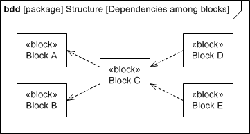
Though you didn’t ask, I’ll add: it’s also permissible to have multiple clients depend on a single supplier. For example, Block D and Block E both depend on Block C. If Block C changes, then Block D may have to change, too. If Block C changes, then Block E may have to change, too. Again, each relationship is complete by itself.
With regard to the second part of your question (in parentheses): a satisfy relationship is simply a specialized kind of dependency–one that’s created from a client element (which is almost always a block, by convention) to a requirement. Thus, everything that I stated above about a dependency applies to a satisfy relationship, too. A single block can satisfy multiple requirements, and multiple blocks can satisfy a single requirement (as shown in the requirements diagram below).
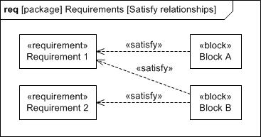
Please remember, once again, that each satisfy relationship is complete by itself. The model shown above conveys that each instance of Block A will satisfy Requirement 1. It conveys also that each instance of Block B will satisfy Requirement 1. This model does not convey that it takes an instance of Block A and an instance of Block B together to satisfy Requirement 1. If that’s what you need to convey, then I would recommend creating a higher-level composite block (i.e., a block with composite associations to Block A and Block B) and then creating a single satisfy relationship from that block to Requirement 1.
(As a side note, you could also use shared associations–i.e., hollow diamond–instead of composite associations from that higher-level block. However, the semantics of shared associations are not well-defined in SysML. Your team would need to decide upon a meaning for shared associations and capture that meaning in a Modeling Standards and Conventions document to ensure that all designers are using shared associations consistently in your system model.)
Let me end with a focus on the original topic: dependencies. The key thing to remember about dependency relationships is that you use them in a system model to establish traceability among design elements. Begin with the axiom: change happens. At some point during the system life cycle, you will need to modify your system design. When that moment comes, you can use a modeling tool to perform automated downstream impact analysis. And dependency relationships are one mechanism to achieve that. For example, with the model shown above, I could click on Block A (in a modeling tool window) and query the model to generate a list of dependent elements. In moments, the modeling tool would pop up a search results window that displays the transitive downstream tree of dependent elements: Block C, Block D, and Block E (along with all of the other elements in the system model that depend on Block A that are not shown on the BDD above). The modeling tool removes the cognitive burden on you, the designer, in having to remember which client elements may need to be updated each time you make a change to an element in your design. This is one of the many ways that the practice of model-based systems engineering (MBSE) helps engineers ensure the integrity and consistency of their designs when change happens over the course of the system life cycle. And this is the root of the return on investment that MBSE offers over the traditional document-based approach to engineering.
Question 6:
In Module 3, “Internal Block Diagrams,” you introduced an “Item Flow.” It is not mentioned on your “Elements of Definition” chart or “Elements of Usage” chart. Is there a reason for this omission?
Answer:
An item flow is neither an element of definition nor an element of usage. To state this formally using proper SysML jargon, an item flow is neither a classifier nor a typed element. It’s the SysML extension of a UML information flow, which is simply a type of directed relationship.
Now I’ll revert back to mortal speech: an item flow is not itself an element of definition, but it can have one or more elements of definition associated with it–specifically, the names of blocks, value types, or signals that you’ve defined somewhere in your model. These associated elements of definition appear in a comma-separated list, floating next to the item flow on an IBD.
Question 5:
What does the tool “do”? We create all of these diagrams, I understand that, but then what? I read or heard that some people have actually created “executable” models. Does that mean that their models actually produce code? Or what does happen when they hit the “start” button?
Otherwise, how is a model used? I’m sure that each product is slightly different, but do they produce reports on the model status, model completeness, etc.? For example, we define constraints, such as hard drive capacities, and then associate usage instances, so does the model report that the hard drive is too small if there are too many instances? I understand how the block diagrams are viewed by different stakeholders, but there has to be more to it than that. For example, what about power and weight budgets for the satellite project?
Since this course is for the exam only, is there another course that you’d recommend about the basics of MBSE, or perhaps a book/white paper?
Answer:
Let me answer your questions in small chunks:
What does the tool “do”? We create all of these diagrams, I understand that, but then what? I read or heard that some people have actually created “executable” models. Does that mean that their models actually produce code? Or what does happen when they hit the “start” button?
Yes, some modeling teams do autogenerate source code from their UML and SysML models. All of the commercial-grade (i.e., not free) modeling tools on the market today have editions that offer code generation and code reversal capabilities–for various programming languages: C, C++, C#, and Java. The specific tool chain and mechanics of the workflow vary, but generally you will integrate your UML/SysML modeling tool with an Integrated Development Environment (IDE) (e.g., Netbeans, Eclipse, Visual Studio). The UML/SysML modeling tool translates the system model into source code in a programming language of your choice, and the IDE compiles that source code into an executable. Then you run that executable on a target platform (or simulator) like you would for an executable whose source code you produced by hand. In many cases, the integration mechanism between the modeling tool and the IDE enables you to run the executable, provide inputs, and display outputs directly in the modeling tool window. So in short: yes, modeling tools allow you to both build and execute a system model.
Otherwise, how is a model used? I’m sure that each product is slightly different, but do they produce reports on the model status, model completeness, etc.?
I’ll begin with the most basic and yet most value-added use for a system model: visualization and communication of a system’s structure, behavior, requirements, and constraints among stakeholders. The greatest share of the return on investment from MBSE comes from the most basic thing that we do on the MBSE path: creating a system model–which serves as an integrated, centralized repository to capture your system design decisions. The system model serves as the single source of truth that you go back to when (not if) change happens. And when that time comes to make a change, you make the necessary change one time in one place within the system model…and the modeling tool automatically propagates that change to all of the places where it’s needed (i.e., other model elements that have a relationship with the one you changed as well as all of the diagrams where the changed element appears). And this is a non-trivial benefit. The modeling tool removes the cognitive burden on you, the designer, in having to remember which client elements and diagrams need to be updated each time you make a change to an element in your design. There is no opportunity for inconsistency among the various views that you create of the underlying system model. MBSE yields ROI for one simple reason: the cheapest defect to fix is the one you prevent.
I understand the impulse to want the modeling tool to “do” something (e.g., generate reports, design documents, and source code). Each of these capabilities certainly adds more value–generates cumulatively greater ROI. But again, the greatest share of the total ROI comes from the most basic of MBSE activities: creating a system model–both to serve as the central record of authority for your team’s system design decisions…and to maintain the integrity and consistency of the system design when change happens over the course of the system life cycle.
Once your team becomes comfortable with this activity, you can advance incrementally to higher modeling maturity levels: defining, capturing, and reporting system model metrics; defining and applying domain-specific languages (DSLs) to your system model; simulating your system by integrating the modeling tool with an IDE to generate source code and execute the model; performing engineering analyses by integrating the modeling tool with an equation-solving tool. You can use a system model in all of these ways, for all of these purposes. But we model primarily to visualize and communicate our system’s design to our stakeholders.
For example, we define constraints, such as hard drive capacities, and then associate usage instances, so does the model report that the hard drive is too small if there are too many instances? I understand how the block diagrams are viewed by different stakeholders, but there has to be more to it than that. For example, what about power and weight budgets for the satellite project?
Now you’re touching upon the idea of using a system model to perform engineering analyses. The short answer is: yes. You can use the parametric modeling capability defined in SysML to build a mathematical model of your system–a set of constraints (in the form of equations and inequalities) that serve two purposes:
- assertions about the values that are valid in a system that’s operating nominally (and thus, the capability to detect exceptional conditions when they occur)
- building blocks to create engineering analyses that you can run during the design stage of the systems life cycle (if your modeling tool is integrated with an equation-solving tool)
The kinds of analyses that you described above are standard fare for SysML parametric models.
Since this course is for the exam only, is there another course that you’d recommend about the basics of MBSE, or perhaps a book/white paper?
Respectfully, I must correct the misunderstanding that is the premise of your question: my online SysML course is not for the exam only. There are two objectives in this course:
- develop the SysML proficiency you need to be a contributing member on an MBSE team
- develop the SysML proficiency you need to pass the OCSMP Model User and OCSMP Model Builder: Fundamental certification exams
I provided an overview of MBSE and SysML in the live webinar that I advertised and delivered as a precursor to this 14-week online SysML course. That webinar is where I discussed many of the points that I made here. I am currently offering that webinar as an on-demand recording for those who missed the event. If you would like to watch that on-demand recording, you can register for access using the following link:
Question 4:
Can you have a generalization between 2 abstractions (i.e., a Star Sensor is a Sensor. A Sensor is a piece of Hardware)?
Answer:
If I may, let me begin by restating the question to clarify what I believe you intended to ask:
Can you have a generalization between 2 abstract elements (i.e., a Star Sensor is a Sensor. A Sensor is a piece of Hardware)?
And the answer to this question is: yes. Here’s the SysML translation of your English statements (in parentheses above):
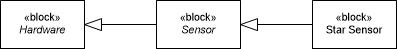
It is legal in SysML for one abstract element to be a subtype of another abstract element. For example, Sensor is a subtype of Hardware (and both are abstract elements in this model).
Now that I’ve directly answered the question, let me clarify the distinction between the terms “abstract” and “abstraction”:
“Abstract” is the term (in SysML) that refers to any element of definition (e.g., block, actor, use case, activity, interaction, state machine) that you create in a system model and declare to be uninstantiable. (I’ll elaborate on this concept in the next paragraph.) “Abstract” is simply a property that you can toggle on and off for any classifier in a system model (where “classifier” is the formal SysML term for any of the various kinds of elements of definition). When you set the “Abstract” property for a classifier in your system model, the name of that element will be displayed in italics on diagrams. The figure above conveys that I’ve set the “Abstract” property for the Sensor block and the Hardware block in my system model.
So what exactly does it mean for a classifier to be abstract (i.e., uninstantiable)? It means that the modeler does not intend for there to be any instances within a built and operational system that are directly typed by that classifier. For example, the model above conveys that there will not be any instances that are directly typed by the Sensor block; all instances of sensors in my system will instead be directly typed by a subtype of Sensor (e.g., Star Sensor, Gyroscope, Magnetometer, Sun Sensor, Earth-horizon Sensor). An abstract element exists in a system model solely to serve as a supertype for a set of subtypes. And with that, I can return to my original point: the distinction between the terms “abstract” and “abstraction”:
“Abstraction” is the term (in English) that refers to any representation that selectively hides details to make dissimilar things look similar. At the macro level, a system model in its entirety is itself an abstraction of one or more systems that you will build and deliver to customers. Each of those built and delivered systems may have differences among them that are introduced in the development and production stages of the systems life cycle. In the system model (i.e., the abstraction of those built and delivered systems), you will selectively omit any details that you, the system designer, deem to be nonessential–details that you choose to leave to the discretion of the development and production teams.
At the micro level–within a system model–you may create a set of classifiers that all share a common set of features (i.e., part properties, reference properties, value properties, constraint properties, ports, operations, receptions). You could add that common set of features to each of those classifiers, but that would violate the spirit of model-based systems engineering (i.e., one fact in one place) and increase the time and cost required to maintain and evolve your system design over the course of the system’s life cycle. You should instead factor out that common set of features and place them in a supertype; all of the original classifiers then become subtypes of that supertype–and by definition, they inherit the common set of features that you placed in the supertype.
My point? You can refer to any supertype as an “abstraction” of its subtypes…whether or not a given supertype happens to be an “abstract” element in your model.
Question 3:
Regarding your checkpoint question 1-9: the question asks “How many structural features of the Flight Computer block are displayed in this figure?”

You stated that the correct answer was “F) 6.” Early in the lecture, you stated that there are 5 types of Structural Features (Part Properties, Reference Properties, Value Properties, Constraint Properties, and Ports). When we got to the part of the module on Ports, you said there are two kinds of Ports – Standard Ports and Flow Ports. This seems to imply that the kinds definition is a sub-classification of the Ports structural feature. Based on how this question is worded, it seems to imply that the maximum value one could possibly come up with is 5, which is what I assumed was the right answer when reading the question (with the two kinds of ports shown on the block still both counting as representations of the same feature – Ports). What am I missing?
Answer:
If the question had asked, “How many types of structural features are displayed in this figure?,” then the correct answer would have been “5.” As you pointed out, the nonatomic flow port and the standard port shown would both count as a single type of structural feature: ports. But the question instead asked, “How many structural features…are displayed in this figure?” It’s asking for the number of instances, not types. The nonatomic flow port and the standard port are two distinct instances of the SysML concept known as “port.”
To put this in formal terms–for those of you who are ready to find out how deep this rabbit hole goes–the UML and SysML metamodels (i.e., the abstract syntax of the language) contain the metaclass called Port. A metaclass is simply a definition of a language concept. You, a model builder, then create a system model, which contains a set of model elements. Each model element you create in a system model is an instance of a metaclass. So…to circle back to your question: the nonatomic flow port and the standard port shown in the figure are two distinct model elements (i.e., two distinct instances of the Port metaclass). Question 1-9 is asking you to identify the number of structural features (i.e., the number of model elements that happen to be instances of the Structural Feature metaclass).
You don’t need to know these formal terms, metamodel and metaclass, to pass the OCSMP certification exam. But you do need to be able to make the distinction between the number of subtypes of a language concept (e.g., the five types of structural features defined in SysML) and the number of instances of a language concept (i.e., the number of model elements that happen to be structural features in a given system model).
Sorry for the word salad. I warned you that this rabbit hole goes deep. I hope this explanation helps.
Question 2:
You stated in Module 1 of this online course that any block can have two types of features, namely, structural and behavioral. Now, we know that behavioral features include operations and receptions. However, we also have standard ports, which are categorized as structural features. And you told us that standard ports represent operations and receptions. So why then do we categorize standard ports as structural features and not as behavioral features?
Answer:
To clarify a point: a standard port does not represent a set of operations and receptions. Rather, a standard port represents a distinct point of interaction at the boundary of a block. As such, it is a structural thing. For example, think of a pipe fitting at the boundary of a pressure vessel or an HDMI jack on the boundary of an LCD television.
Now for the more precise explanation: a standard port represents a distinct point of interaction at the boundary of a block through which clients of that block can access a provided interface (i.e., a defined set of operations and receptions that the block implements)…or through which that block can access a required interface (i.e., a defined set of operations and receptions that it needs from some external structure).
But that’s not equivalent to saying that a standard port represents operations and receptions. There’s a degree of separation between these concepts in the SysML grammar (i.e., the abstract syntax of the language):
1. A block can own one or more standard ports, which are structural features.
2. A standard port can be typed by one or more interfaces.
3. An interface can own one or more behavioral features (i.e., operations and receptions).
Now that I’ve answered the question, I feel compelled to offer this reminder, too:
Standard ports (and flow ports) were defined in SysML v1.2 and earlier. As of SysML v1.3, they are deprecated and replaced by the concept of a port, which unifies the semantics of standard ports and flow ports. SysML v1.3 also defines two extensions to this unified port concept: full ports and proxy ports, which I discuss in detail in Appendix B of SysML Distilled. I discussed standard ports and flow ports in Chapters 3 and 4 of SysML Distilled (and I’m discussing them in this online course) only because the current versions of the OCSMP certification exams still cover these topics.
Question 1:
Do we always have to implement Standard Ports as compatible ports? Like in Figure 3.9 in SysML Distilled, we have Power Generation shown as a provided Interface on the EPS side and as a required Interface on the CDHS side:
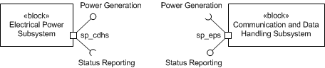
Am I right in understanding that Power Generation is one interface for which we need to have one client (or caller) as we may call it, which happens to be CDHS in our model and one provider, which is EPS?
Answer:
An interface is an element of definition; it commonly defines a contract of behavioral features (i.e., operations and receptions). In your system model, you could potentially have multiple blocks that provide a given interface and multiple blocks that require that same interface. Defining an interface serves two purposes:
1. Reusability. You define a set of operations and receptions (that multiple blocks provide or require) in a single place in your model hierarchy. When the time comes to make a change to that contract–that set of operations and receptions–you go back to that one place in your system model and you make the change one time. By contrast, if you add that (common) set of operations and receptions directly to each block that provides it, you would have to update all of those blocks each time you make a change to an operation or reception in that common set.
2. Encapsulation (and its corollary, loose coupling). An interface hides the details of a provider’s internal implementation. A client only knows the interface (i.e., the contract of services) it requires. It is agnostic about which provider (among potentially many providers) performs those services for it. And it is agnostic about the internal implementation of any given provider that is performing those services for it. Encapsulation (and loose coupling) offers two advantages:
a. The ability to substitute one provider for another dynamically within an operational system. Think of a satellite that has two power sources installed: solar panels and batteries. Both can perform the same service: provide power. The solar panels provide power to the satellite’s distribution bus when the satellite is in line of sight of the sun and the batteries provide power to the satellite’s distribution bus when the satellite is in eclipse. With respect to the client–the distribution bus–the specific provider is dynamically substitutable.
b. Efficient maintenance and evolution of a system design. When stakeholder requirements change over the course of the system life cycle and the design team needs to evolve the system design (e.g., adding new providers of a given interface or modifying the internal implementation of an existing provider of a given interface), that design change is transparent to all of the clients of that interface. To put this another way, the design team does not need to spend any man-hours modifying the clients of an interface each time a provider changes.
With all of that background knowledge in place, I will now directly answer your question:
No. Your system model does not necessarily have to have a provider and a client for each interface you’ve defined. You might create a model library of interfaces with the intent to reuse subsets of them in multiple system models. In any given model, therefore, there may be an interface in that model library that doesn’t get assigned to any blocks.
But…if you do assign an interface to a block (or an actor) as a required interface, then there should be at least one other block (or actor) somewhere in the system model that has that same interface assigned to it as a provided interface. If you don’t, then you have an element in your design whose needs aren’t being met–either by another part of the system or by an actor in the system’s external environment.